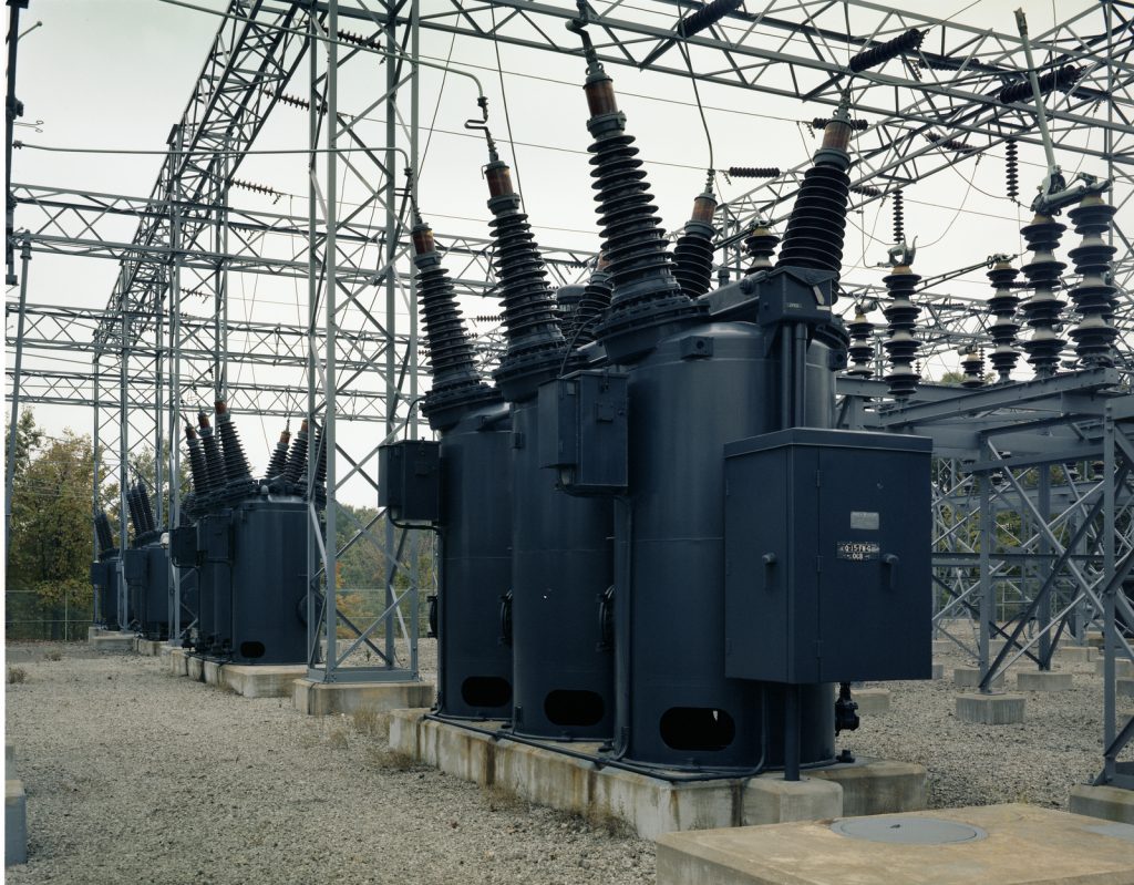
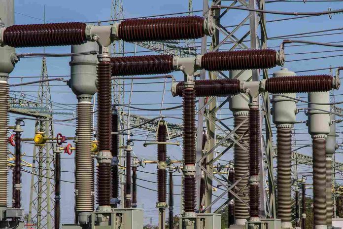
The transformer is a common part of electronic and electrical devices. Michael Faraday discovered electromagnetism in the 18th century, which makes it an electromagnetic device. All transformer types follow the same principles, but their construction methods are different. Transformers are electrical devices that transfer electrical energy from one circuit to another through electromagnetic induction. There are several different types of transformers, each with unique features and applications.
One type of transformer is the power transformer, which is used to step up or down voltage levels for power distribution. Distribution transformers distribute power to homes and businesses at lower voltages. Instrument transformers, such as current and potential transformers, are used to measure current and voltage in electrical systems. Autotransformers are a special type of transformer that has a single winding and is used for voltage regulation. Isolation transformers separate two circuits for safety or to eliminate noise. Another type of transformer is the audio transformer, which is used in audio equipment to match impedance and transfer signals between stages.
It is also possible with a little effort to build your transformer, but one should always practice transformer protection techniques when building their transformer. In this section, we will discuss different types of transformers.
Types of transformer
Electrical power systems use different transformers for various purposes, such as generation, distribution, transmission, and utilization.

Transformer with air core
The primary and secondary windings are wound on a non-magnetic strip, so the flux is transferred between the two windings by air.
The mutual inductance of an air core is lower than that of an iron core, i.e., the reluctance offered to the flux generated is higher in the air medium. However, the air-core type transformer eliminates hysteresis and eddy current losses.
Transformer for instruments
They are commonly referred to as isolation transformers. The secondary winding of instrument transformers, in most cases, will be safely isolated when the primary has a high current and voltage. Transformers can be divided into two categories:
- The Current Transformer (CT)
- The Potential Transformer (PT)
A dry type of transformer
Unlike wet-type transformers, dry-type transformers do not use any insulating liquid to insulate their windings or cores. Windings and core are instead contained within an air-filled tank that is sealed. Windings and core are still very safe without liquid.
An oil-immersed transformer
Read more:Each And Everything You Should Need To Know About Consumers Unit
This type of transformer is also known as a transformer filled with oil. A transformer with an oil-immersed cooling system reduces the temperature of the transformer by using oil cooling. A transformer with a weld-steel oil tank filled with insulation oil is different from a dry-type transformer because its body is immersed in insulation oil.
The coil and iron core convert the heat produced by operation first into insulation oil, then into a cooling medium. Depending on the transformers capacity sizes, they can be classified as immersion natural cooling transformers or forced air cooling transformers.
The transformer of the Berry type
Berry type transformers are generally distributed core transformers of the shell type. Because the magnetic core of this transformer is similar to a wheel’s spokes, the construction of this transformer is similar to a wheel’s spokes. The rectangular arrangement of these cores makes this transformer look like an automobile. Due to the distributed magnetic lanes in this type of transformer, the number of magnetic lines in this type of transformer is more significant than the two that are independent.
Under this structure, the transformer oil can cover the whole thing, and also metal sheets can be used tightly connected to cover it. It is advisable to connect the steel plate of the metal tanks with a solid structure, especially if the plate is of high quality. To insulate the transformer, the oil can be filled through the transformer.
The Step-up transformer
Transformers have windings wound over the core and are designed to carry currents. These insulated windings are made to endure operational and testing circumstances while also insulating the transformer. Copper or aluminum is used for the windings. While the secondary windings are made up of thin wires with many turns, the primary windings are made up of thick wires with fewer turns on the core.
The step-up transformer provides increased voltage on the output side since the number of turns on the secondary is always greater than those on the primary. Therefore, the secondary side of the transformer is developed at a high voltage.
The primary side of transformers in India is developed at 11kV. Generally, AC power is transmitted over long distances using high voltage (220 – 440 volts). A step-up transformer is employed at the generating station to transmit AC power over long distances.
The Step-down transformer
By stepping down the output voltage, a transformer reduces the output voltage. Essentially, the power is converted from high to low voltage and from low to high current. Unlike the power supply, the doorbell only needs 16v rather than the power supply’s 230-110v. For this reason, it is recommended to reduce the voltage from 110v or 220v to 16v using a step-down transformer.
Molecular potential transformer
Molecular voltage transformers are also known as potential transformers. They are connected to a high voltage line through their primary winding. The secondary side of the transformer is connectors to be measured.
Potential transformers have the primary function of stepping down voltage levels to a safe level. A potential transformer has an earthing point or ground for its primary winding.
The primary to secondary voltage ratio is given as 500:120, which means that when the primary is applied to 500 V, the secondary will output 120 V.
Transformer with two coils
Transformers based on windings include two different windings per phase, such as primary and secondary. Here, the primary winding utilizes AC input, whereas the secondary is connected using a load. Although these windings are electrically separated, they are magnetically coupled.
The induced EMF (Electromotive Force) is caused by the variable magnetic flux resulting from the changing current within the primary winding, referred to as mutual induction during the secondary winding. That’s why the voltage is induced on the O/P side of the transformer. Input voltage mainly depends on the winding ratio, which can either increase or decrease.
Automated transformer
A common winding is used for both the primary and secondary windings of these transformers. Three taps are located at the three points where the autotransformer winding makes electrical connections. A typical transformer is more extensive and heavier. An autotransformer is lighter, smaller, and cheaper.
Electrical isolation is not possible between the primary and secondary circuits due to this device. As well as reduced leakage response, decreased losses, reduced excitation current, and increased VA ratings, they also have lower mass and size requirements.


